Assembly
For CAD and Zemax files, check out the following GitHub repository: https://github.com/spacetelescope/BabyCAT.
Unfolded Optical Layout
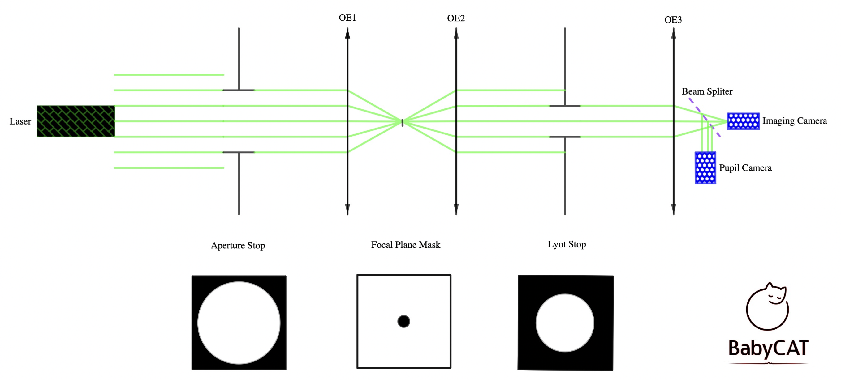
BabyCAT contains a classical Lyot coronagraph with a Lyot stop adjustable in diameter. The unfolded optical layout is shown below. In this setup, the three optical elements 1-3 (OE1, OE2, OE3) are spherical mirrors with focal lengths of 200 mm, 200 mm, and 150 mm, respectively.
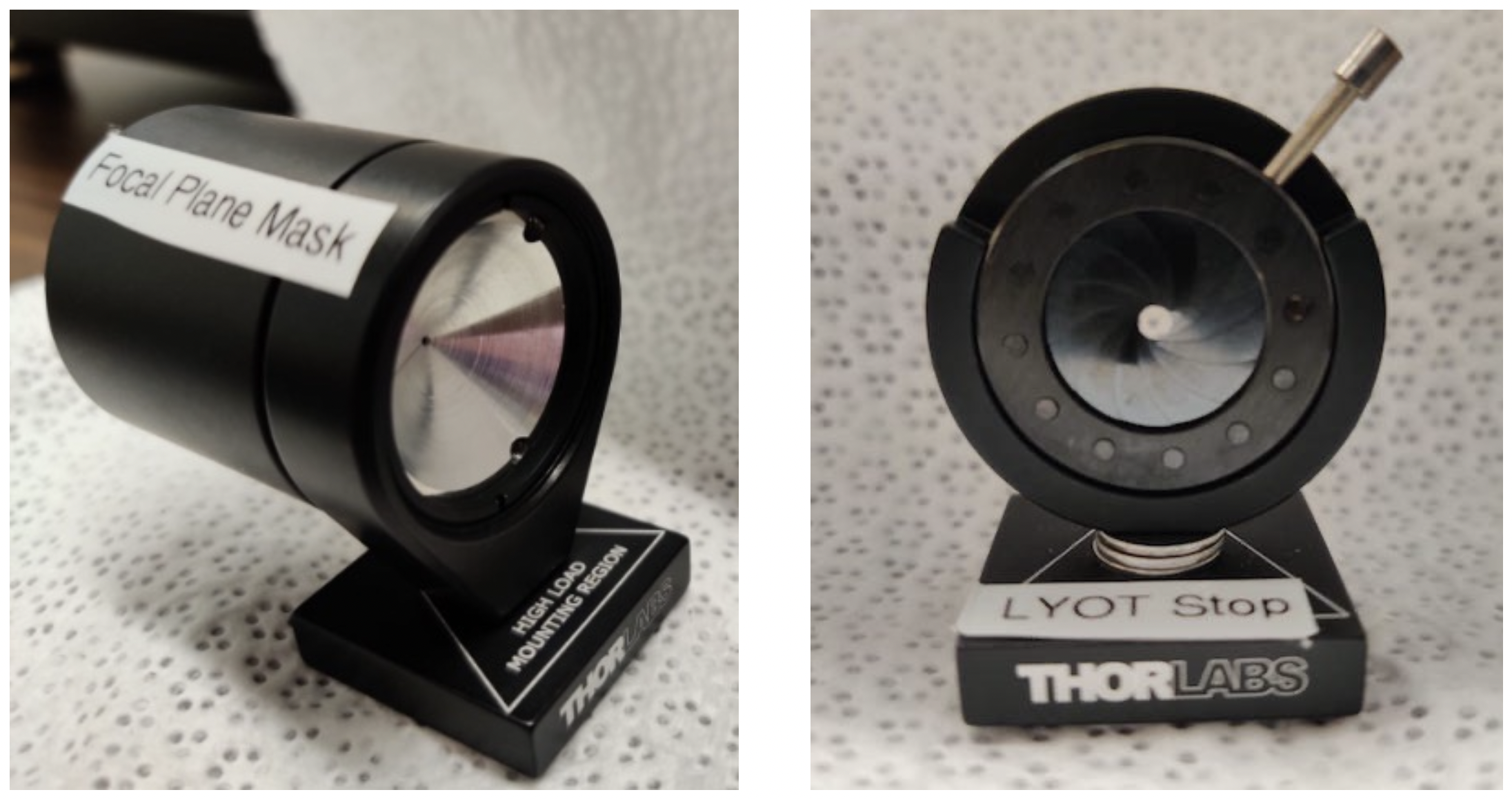
Below, you can see close-up images of the reflective focal-plane mask (FPM, left) and the Lyot stop (LS) iris (right) on their respective magnetic mounts.
Mechanical Schematic
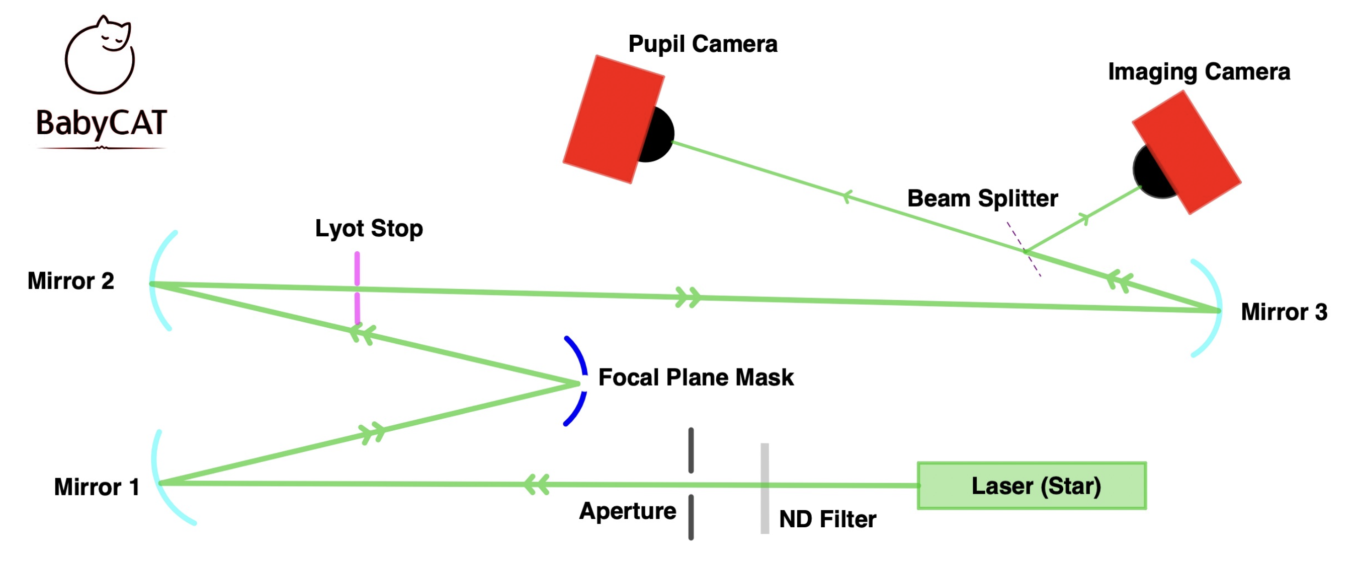
The below is a schematic of the general layout of the demo coronagraph.
Assembly Outline
The alignment of the demo coronagraph requires some familiarity with standard optical alignment techniques and the use of standard optics mounts, as well as good judgment as to when point-spread functions (PSFs) and images are in good focus. For cost reasons, most mounts in BabyCAT do not have adjustment actuators. As a result, adjustments have to be made by carefully sliding mounts across the breadboard and by sliding posts up and down in post holders. Care is required when performing these movements and when screwing down mounts in their final location.
The final goal is a demonstration that is visually instructive regarding the operation of a coronagraph for exoplanet imaging. Precision alignments may not strictly be necessary to achieve this. However, experience has shown that some care and finesse are needed to align the system well. Otherwise, there will be appreciable aberrations (primarily astigmatism) visible in the system PSF and the “star” light will not be effectively rejected. It is also possible to have a system that is nearly aligned, but a mechanical interference presents itself when attempting to, for example, perform final focusing on the Lyot stop. Multiple iterations of the alignment procedure may be required to achieve good optical alignment without any interferences.
Be sure to have a sheet of lens tissue or a business card on hand so that the beam path can be traced out.
- Set height of optics and laser to match the (arbitrarily set) height of the focal-plane mask (FPM).
- Use the laser to define the initial optical axis, roughly aligning the system aperture and the first spherical mirror to the beam.
- Set the relative positions of the FPM and first spherical mirror, and the tip and tilt of the spherical mirror.
- Roughly align the FPM aperture to the focus produced by the first spherical mirror. Auxiliary optics (re-imaging lens) are used to image this onto one of the cameras (temporarily placed). The tip and tilt of the FPM also need to be adjusted at the same time to make sure that the reflected beam falls in an appropriate location on the second spherical mirror.
- Adjust the position and tip/tilt of the second spherical mirror so that the beam is roughly collimated and passes near the FPM, roughly parallel to the long axis of the breadboard.
- Place the Lyot stop (iris) so that it is roughly concentric with the beam after reflection off of the second spherical mirror. The Lyot stop should be placed closer to the breadboard side of mirrors 1 and 2 than the FPM.
- Adjust the position and tip/tilt of the third spherical mirror so that an image of the system aperture is formed on the pupil camera at a convenient location on the breadboard.
- Insert the beam splitter and direct the beam so that the reflected beam forms an image of the “star” on the imaging camera.
- Adjust the final focus of the system aperture on the pupil camera, and then adjust the focus and positioning of the Lyot stop.
- Adjust the final focus of the FPM and image on the imaging camera. This requires iterating between the position of the FPM and the position of the camera and great care must be taken here to avoid knocking the system out of alignment.
- Check to make sure that a good coronagraphic image is formed when the FPM is blocking the beam and the Lyot stop is closed down.
- Final tweak of alignment and verify operation.
Realignment
General Realignment Procedure
- Set laser height to match focal-plane mask (FPM) height.
- Place laser on table facing the positive optical axis.
- Place first spherical mirror such that the beam falls relatively close to the edge interior edge of the second mirror. This helps reduce angles of incidence and minimize astigmatism. (Note that in an already assembled system, the beam will not reach the edge of the mirror as the path will be obscured by the Lyot stop mount first.)
- Adjust the first spherical mirror in the tilt direction to center the beam vertically on the FPM.
- Adjust the lateral position of the FPM to align the beam with the pinhole.
- Adjust pupil camera such that it is perpendicular to the beam path. Use a transmissive paper to establish beam path and ease centering on the camera.
- Adjust pupil camera to establish best focus, using the sharpness of pupil edges as a guide.
Refocusing the focal-plane mask
If the FPM position is not conjugate to the best-focus image plane, the imaging backend will need to be fully disassembled and repositioned. Note that moving the FPM changes the conjugates (object/image distances) for the second spherical mirror and final imaging optic.
- Disassemble the imaging backend.
- Insert a pick-off (flat) mirror and re-imaging lens to acquire an image of the back of the FPM.
- The camera can be brought to focus by finding the plane in which the PSF is best-focused (which will be conjugate to the best focus of the FPM).
- Adjust the FPM position to maintain centering and bring the edges into focus.
- Re-align the imaging backend (may take ~1 hour).
Assembly images
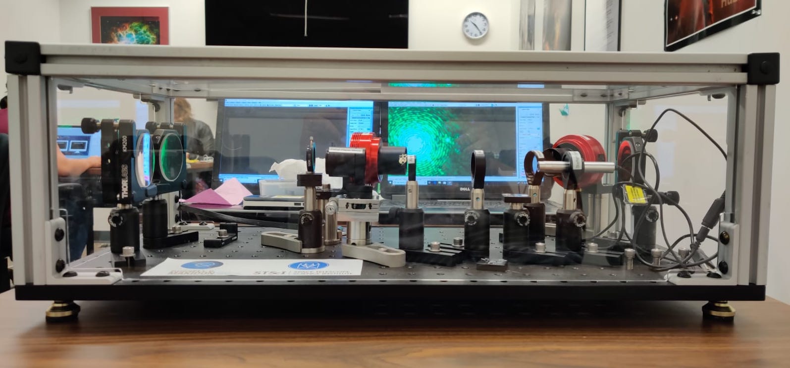
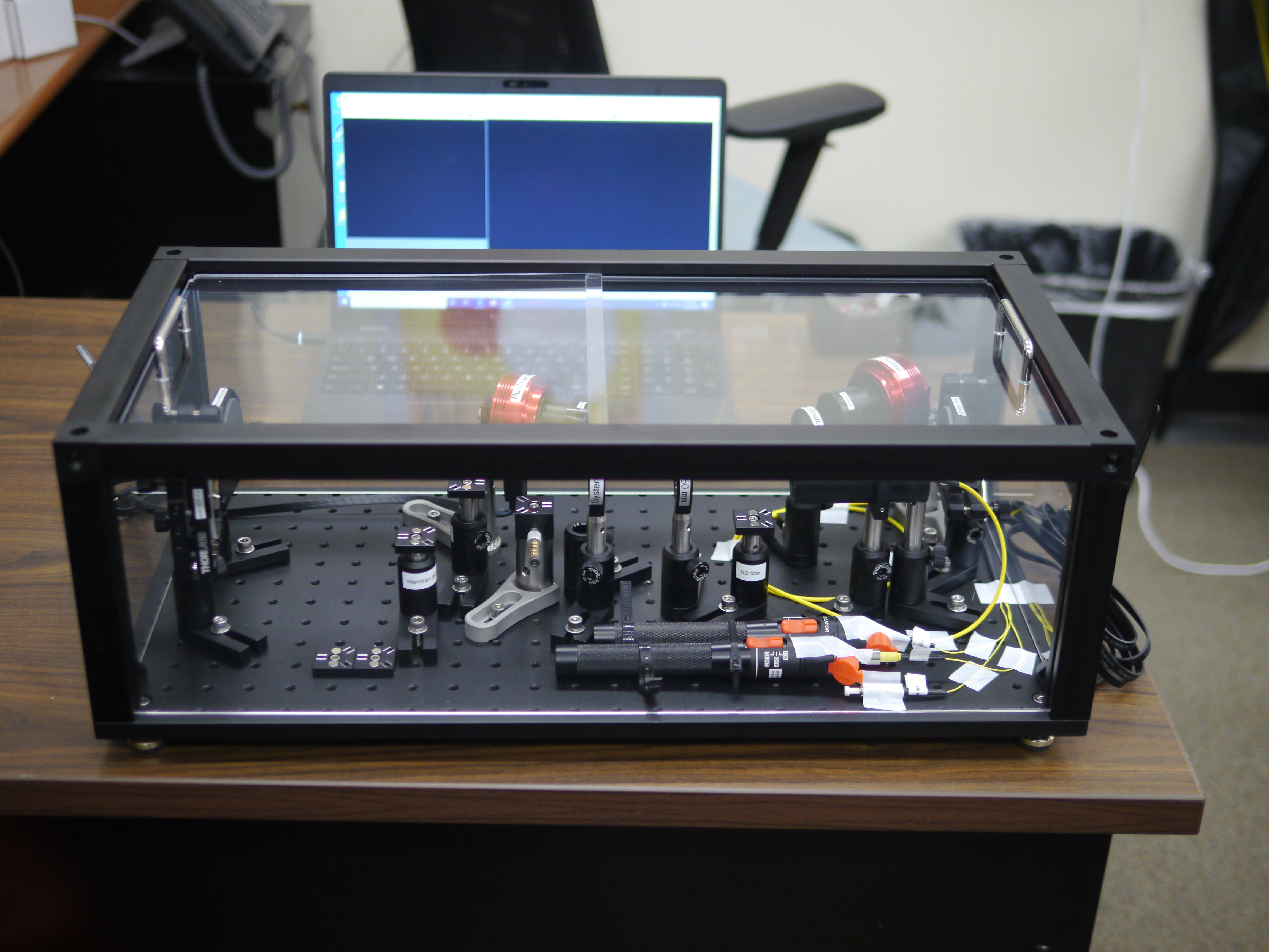
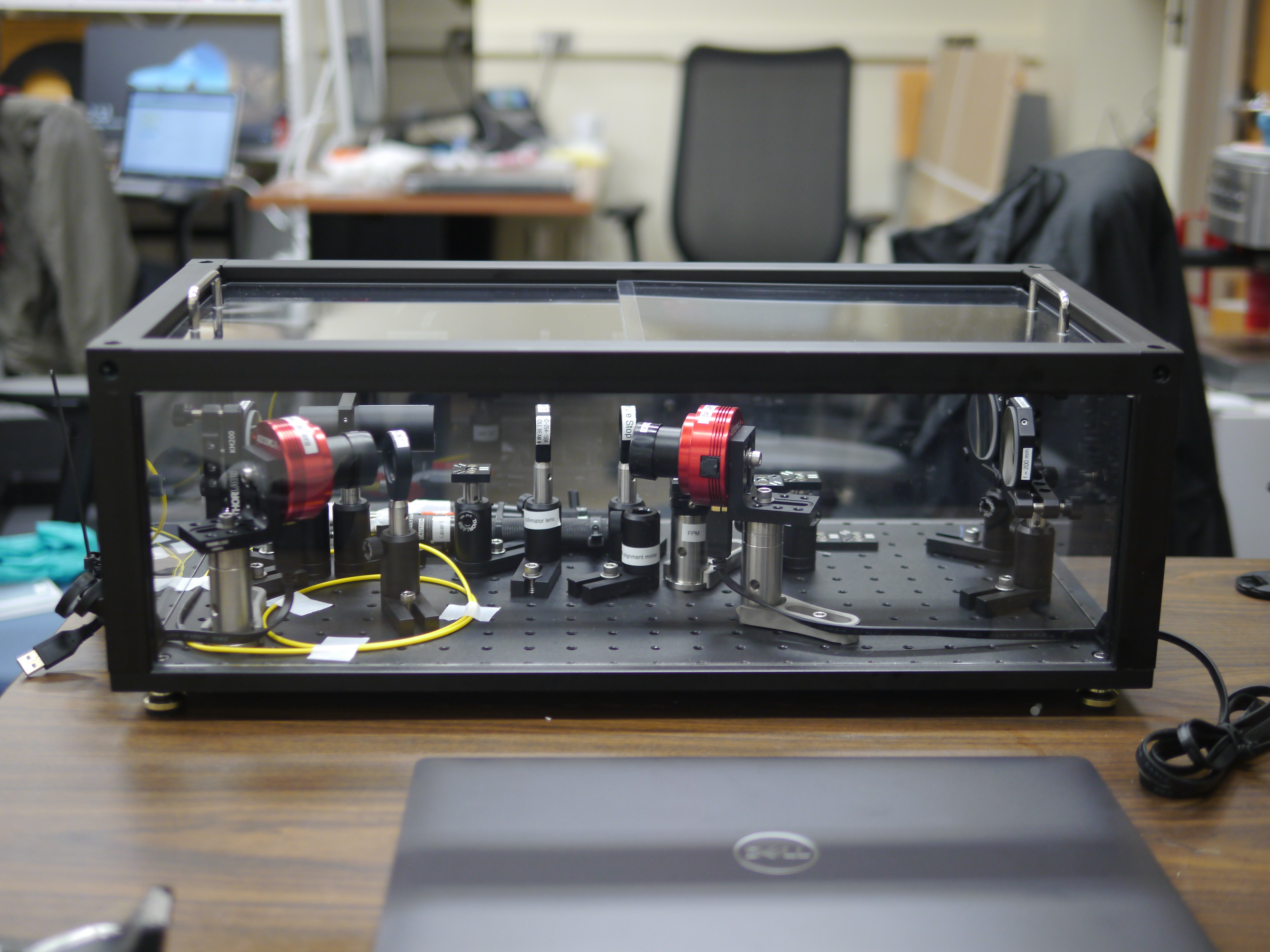
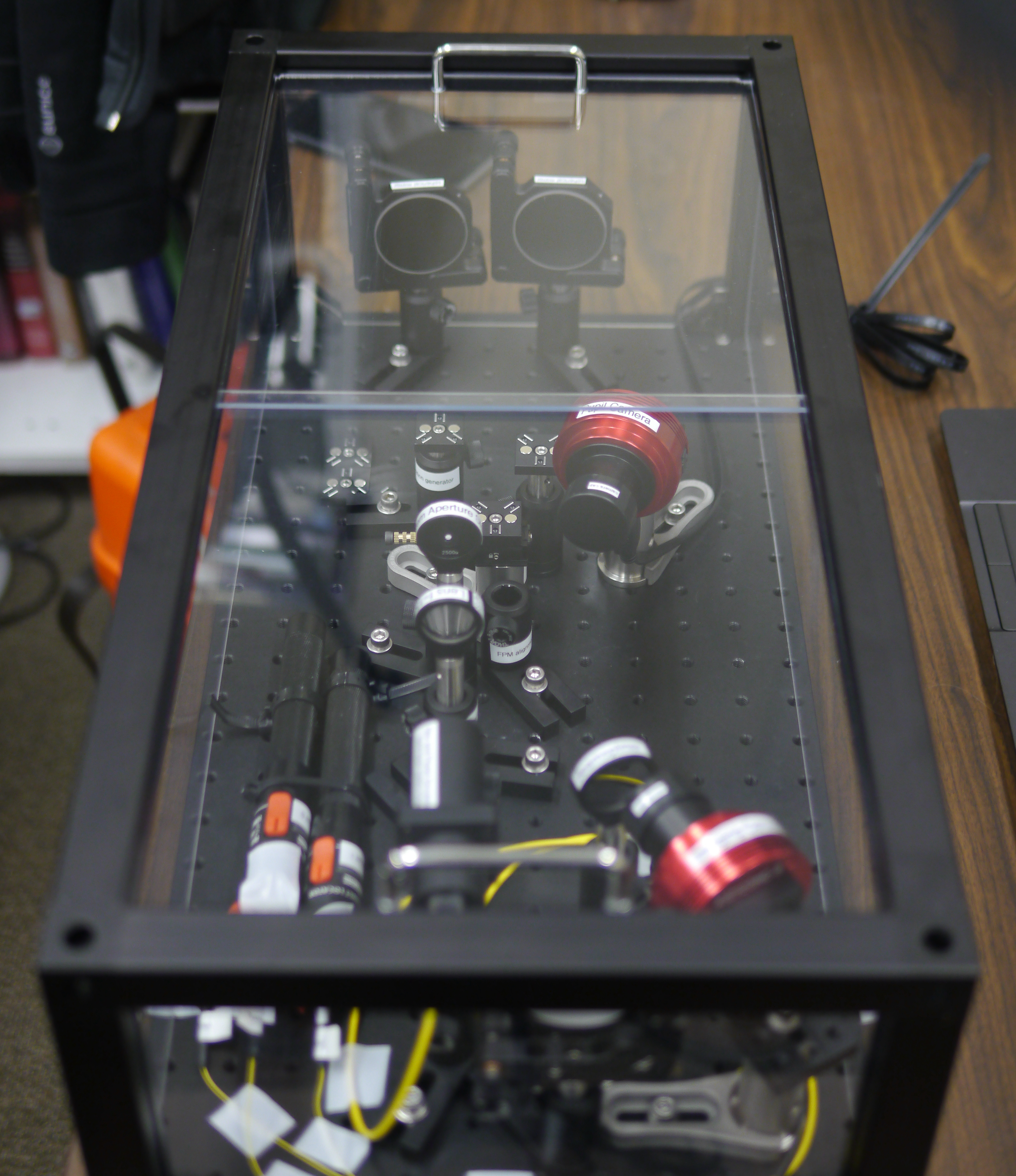
Below you can find a couple of images of the assembled BabyCAT and BabyCAT2 benches. The assembly with a grey frame is BabyCAT, and the assembly with a black frame is the evolved BabyCAT2, on which the parts list of this website is based on.
Keep in mind that the assembly images are for reference only and may not be the most up-to-date version of the benches. For example, the images of BabyCAT show the green laser listed in the parts list, while the images of BabyCAT2 show a custom-built laser.
We also note that in the images of BabyCAT2, the FPM and LS have been removed from their magnetic mounts.
